Ferrite Bead as Parasitic Suppressor?
|
The use of ferrite beads as parasitic suppressors in transistor-based RF power amplifiers seems common, but vacuum tuebe amplifiers all seem to use parallel RL suppressors.
For example, the 2019 ARRL Handbook for Radio Communications, page 17.25 suggests a 47 to 100 ohm resistor in parallel with a coil of 3 to 5 turns of 10 AWG wire with a diameter
of 0.25 to 0.5 inches and 0.5 to 1.0 inches long. A Coil Inductance Calculator shows that
a coil of 5 turns on a 0.5 inch diameter with a length of 1 inch has an inductance of 0.128 uH. This was rounded to 100 nH in parallel with 100 ohms for analysis by
LTSpice as shown in the schematic at the right.
|

|
The impedance of this LR circuit was plotted as R+jX where the green trace is R, and the red trace is X. Below the RL plot is a plot of the impedance of the
Fair-Rite 2661375102 EMI Suppression Bead. The table below compares the two at a
few frequencies. The ferrite bead impedances were done by scaling the curve.
Frequency
(MHz) | ZRL | ZFerrite Bead |
|---|
| 10 | 6+j0.4 | 1+j10.9 |
| 20 | 14.4+j1.6 | 7+j16.8 |
| 40 | 23.6+j6 | 21.2+j29.3 |
| 80 | 40+j20 | 35.3+j32.6 |
| 100 | 45+j28.6 | 38.6+j34.8 |
| 159 | 50+j50 | 45.6+j38 |
| 200 | 61.2+j48.8 | 52.7+j44 |
| 400 | 88.9+j31 | 66.3+j58.7 |
| 500 | 90.8+j28.2 | 70.7+j66.3 |
|

RL impedance plot

Fair Rite 2661375102 impedance plot
|
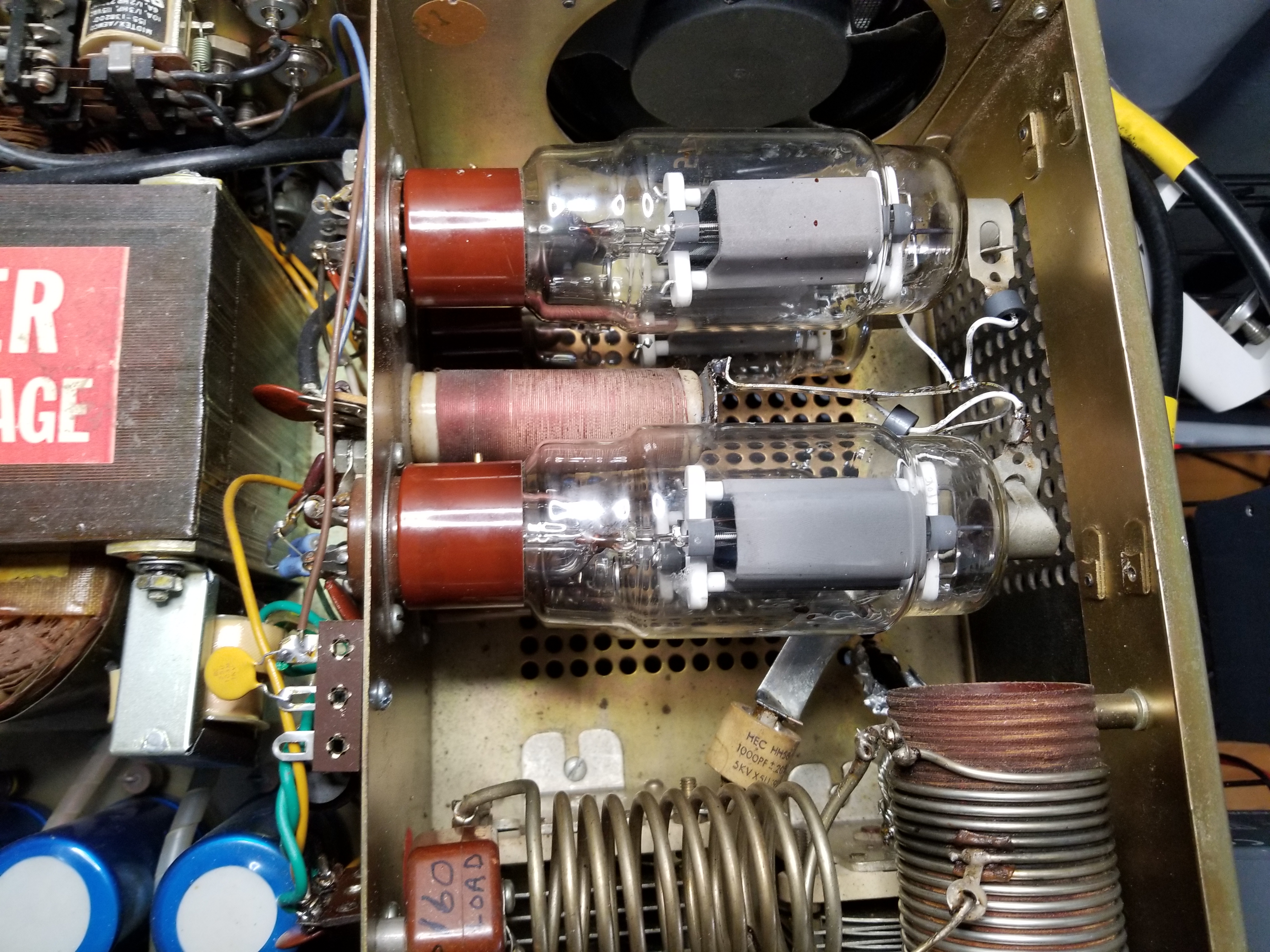
These ferrite beads were tried on a Dentron Clipperton L as shown below. As suggested by W8JI, it is important to have the parasitic
suppressor be the dominant impedance between the tube anode and ground. Originally, the RF path for the tubes was from the anodes, through the parasitic suppressors, through a several inch
wire to the top of the plate choke, then several more inches of thin wire to the DC blocking capacitor on the plate tuning variable capacitor. As modified here, half inch silver plated copper
strap is routed from the top of the plate choke, over to the tube anodes, then to the DC blocking capacitor on the tuning variable capacitor. The plate caps are connected to the copper strap
with short pieces of stranded wire routed through the Fair-Rite 2661375102 EMI Suppression Beads. Tests using
the first W8JI test procedure indicate that the amplifier is stable. It's probably a combination of the use of the ferrite beads and
the copper strap.
Other Resources
Is it practical to use this ferrite bead instead of the typical RL network as a parassitic suppressor? The ARRL Handbook suggestes testing for parasitic oscillationb by running
the amplifier with no input and no load, then varying the output tuning and loading controls through their full ragne on each band. Since there is no RF drive, these controls should
have no effect on the plate current. I intend to try this when I get a chance on by Dentron Clipperton L. I look forward to
any comments.
harold@w6iwi.org
